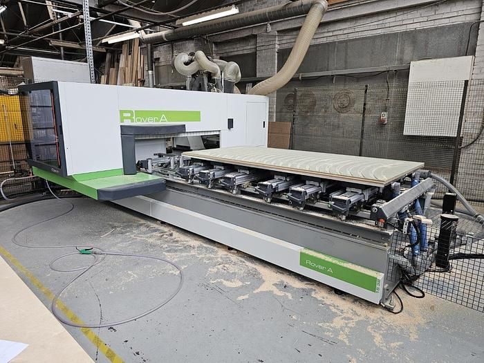

Biesse Rover AS 1532 5 axis
EUROPE (Western and Northern)
Used Biesse ROVER AS 1532
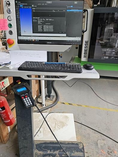
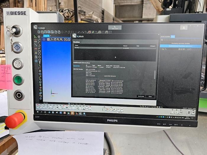
Numerical Control with BSolid Software
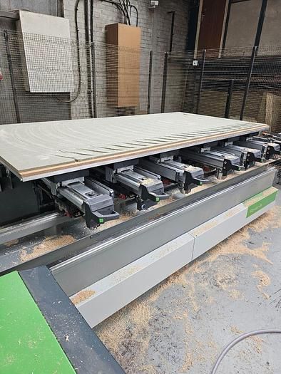
Working range in X axis 3140 mm
Working range in Y axis 1560 mm
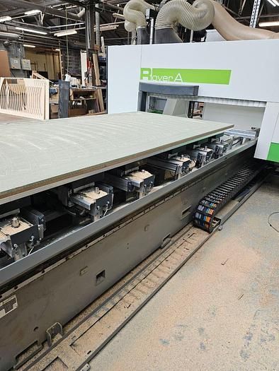
No. 2 work camps
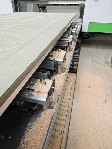
CFT work plan
Bar worktop
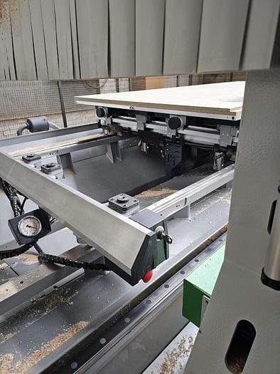
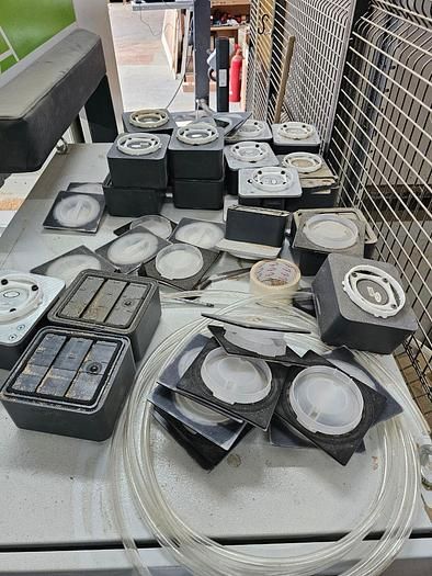
No. 6 adjustable bars for suction cup support
N° 4 pneumatic Bakelite bars for lifting the panel
N° 3 adjustable suction cups for each bar with vacuum seal for fixing the panel during processing
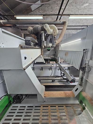
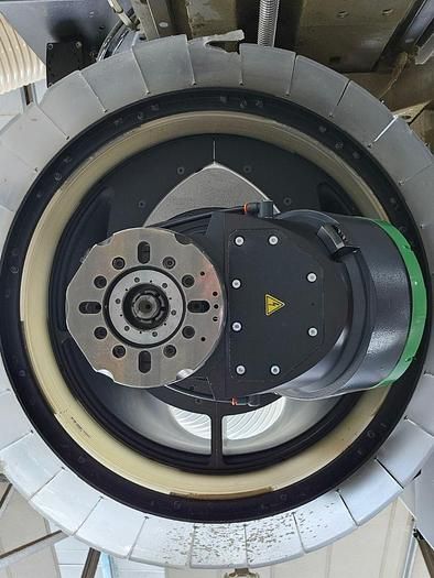
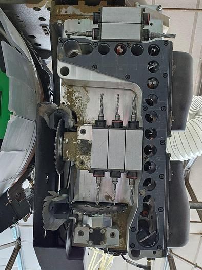
N° 1 5-axis vertical electrospindle, with automatic tool change, liquid cooling, Hsk 63 type cones
Automatic tool change system with 16 positions
Drilling head BHZ 29 2L:
- N° 11 verticals in the X axis
- N° 6 verticals in Y axis
- N° 6 horizontal on the X axis
- N° 4 horizontal in Y axis
- N° 2 integrated blades for making X and Y grooves
Front carpet protection and safety system
Automatic lubrication system
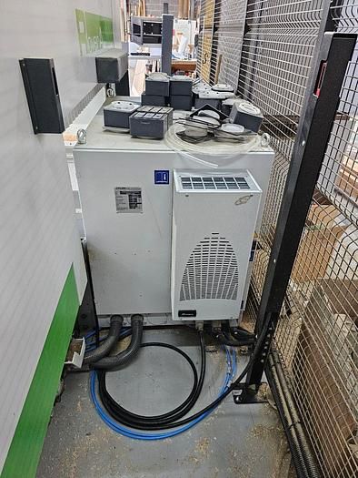
Conditioning system for cooling and cleaning of the machine control
N. 2 vacuum pumps