 1/1
1/1
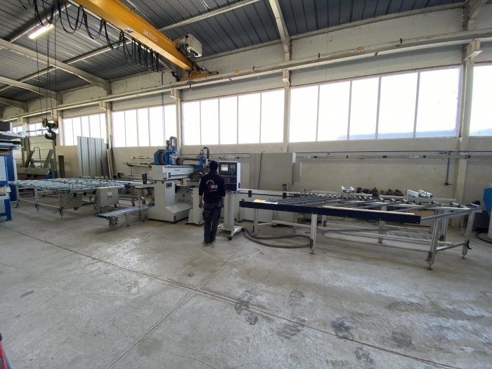
SAPIENS 1001 Joinery Manufacturing Line
EUROPE (Western and Northern)
WORKING PROCESS SAPIENS 1001 Joinery Manufacturing Line
Condition : Used
The Sapiens 1001 TFF machining center is dedicated to sawing, routing and drilling operations of components for the production of windows and doors.
The structure is a type of fixed-gate bridge.
The crossbeam is mounted on rigid and robust columns, which are based on the ground by means of leveling and alignment units, both transverse and lateral.
The base of the column from the part reference side is connected to the central structure of the die, where the clamping systems and the X-axis for part positioning are integrated.
The machine inlet and work areas are equipped with vertical and lateral pneumatic pressure devices,
which allow the parts to be correctly positioned against the lower and lateral reference of the clamping system.
The clamping units slide on the X axis and position the parts in the working areas according to the machining to be performed.
Especially :
*In the first working zone, the position of the part along the X-axis is determined by a microswitch for the on-off movement
*In the second working zone, a reference stop, which disappears automatically, ensures the longitudinal positioning of the workpiece
The X-axis is equipped with 3 clamps as follows:
-the first one is controlled using a pneumatic cylinder
-the other 2 grippers are controlled by the electronic axes X1 and X2, one for each gripper.
The part is generally fed in by an infeed roller against a pneumatic reference stop, in the area of the first gripper.
The first gripper transports and positions the workpiece in the first working area,
while the other two grippers position the workpiece for the second operation in the second working area.
The two grippers are controlled by means of a servomotor and a high-precision rack and pinion system.
Each gripper has safety micro-switches for start and end strokes and mechanical stops against collision.
The electrical board is positioned on the right side of the machine, at the exit of the partand all cables are transported in appropriate cable trays.
The crossbar is adapted to accommodate 2 locations holding the milling heads.
Pin Pos.1 with Y1 axis and Z1 axis.
Pos.2 - Special double rotating head, with A and C axes; the cage slides on the Y2 axis and
Z2 Axis
Each head has a 16-position tool magazine, and in the first unit, a separate position with a pneumatic cylinder allows for changing the saw blade on the head.
The tool magazines have the rotation axis c1 and c2 for correct adjustment.
The work cycle offers the advantage of working with one spindle in a work area while the second spindle is being used for a tool change for the second operation.
Technical specifications:
- Pneumatic pressure: 5 bar
-Min. Part section dim.: 30x18 mmxmm
-Max. Room section dim.: 230x140 mmxmm
-Min. Length w/o rep.: 300 mm
-Max. Part length w/o rep.: 2,800 mm
- Axis travel X1-X2 (clamp): 4,735 mm
-Axis X1-X2 course: 120 m/1
-Y1-Y2 travel: 1,235 mm
-Axis course Y1-Y2: 60 m/1
-Z2 axis travel: 405 mm
-Z1 axis travel: 300 mm
-Z1-Z2 axis travel speed: 45 m/1
-Pressur number hv: 5.5
-Pressure unit thrust: 720 N
-Power of electrospindle HS 652: 10 (ES 779) kW
-Rotation speed: 12,000-18,000 rpm
-Maximum Torque: 8 Nm
-Tool attachment: HSK F63
-ES 919L electrospindle power: 12 kW
-Rotation speed: 12,000/15,000 rpm
-Maximum Torque: 9.5 Nm
-Tool attachment: HSK F63
-Maximum saw blade diameter: 450 mm
-Flange diameter: 140 mm
-Working height: 960 mm
Machine weight: approximately 3600 kg
-Tool Shop Pos. 16, 16, 1
-colours: RAL 7035 light grey
RAL 5015 sky blue
External dimensions: 5710 x 2600 x 2075H mm