 1/1
1/1
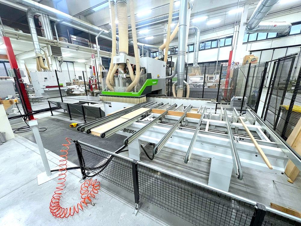
Biesse SKIPPER 130
EUROPE (Western and Northern)
• CNC control on PC basis
• Software BIESSE WORKS
• Useful working field “X” (min – max): approx. 90 – 3,000 mm
• Useful “Y” work field (min – max): approx. 70 – 1,300 mm
• Useful working field “Z” (min – max): approx. 8 – 90 mm
• Panel size X and Y detection system
• Air-veil loading bench
• Nr. 2 Pliers for handling panel
• Transfership straps for unloading panel
• Nr. 2 Mirror drilling heads (Lower and higher) each complete with:
– Nr. 17 (Higher) + Nr. 17 (Lower) Independent spindles for vertical punctures in the direction of “X”
– Nr. 14 (Higher) + Nr. 14 (Lower) Independent spindles for vertical punctures in the direction of “Y”
– Nr. 8 (Higher) + Nr. 8 (Lower) Independent spindles for horizontal punctures in the direction of “X”
– Nr. 2 (Higher) + Nr. 2 (Lower) Independent spindles for horizontal punctures in the direction of “Y”
• Nr. 1 Upper Spindle 4.5 kW (6 HP) ISO 30 connection – Dx and left rotation – Inverter management
• Nr. 1 Lower spindle 4.5 kW (6 HP) ISO 30 connection – Dx and left rotation – Inverter management
• Nr. 1 upper circular blade unit – Diameter 160 mm 3.5 kW (4.7 HP) for cuts and channels in the direction of “X” – Management via inverter
• Nr. 1 lower circular blade unit – Diameter 160 mm 3.5 kW (4.7 HP) for cuts and channels in the direction of “X” – Management via inverter
• Nr. 2 Horizontal drilling/milling groups oriented in dir. “Y” positive
• Copy of original CE Conformity Statement
• Frontal security electronic carpets
• Safety side grids