 1/1
1/1
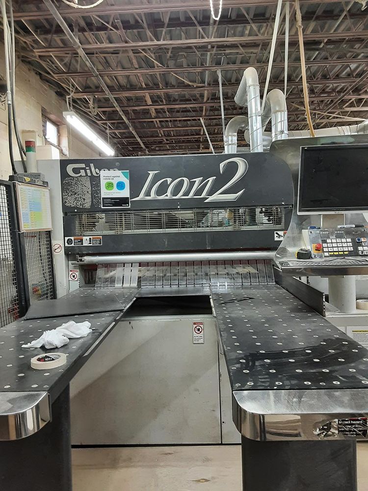
Giben ICON2 h105
AMERICA North (USA-Canada-Mexico)
A UNIQUE ADVANTAGE FOR YOUR FACTORY is represented by the synthesis between high productivity and low occupied space.
THE INLINE SQUARE FENCE with the longitudinal saw, permits a considerable reduction in execution time of the cutting cycle.
TOTAL EFFECT, an angular system, producing greater productivity for its? type due its
COMPACT size and every movement is OPTIMISED.
EASY TO OPERATE, operator has not to handle heavy stacks of panels, he simply directs them to the unloading after the cutting operation.
HIGH VELOCITY of the saw carriage return and the pushers permit the NEW Angular cutting Centre extremely high productivity.
THE CONTROL SYSTEM GDRIVEAXS BASIC guarantees the interface (OPTION) with the optimisation system
GIBEN OPTIWINTM, label printing and other information necessary to formulate the working system justified for the cutting centre.
PRODUCED IN ITALY and delivered to customers worldwide ICON 2 is the synthesis of 40 years experience.
CONFIGURATION OF THE NEW ANGULAR CUTTING CENTER
TECNICAL FEATURES :
-Length cutting machine: 4400 mm
-Cross cutting machine: 1525 mm
-Lift table dimension: 4400x1600 mm
-Working height: 1050 mm
-Control system: G-DRIVEAXS BASIC
-Left handed
-Loading method on lift table: From side conveyor
-Max. opening of grippers: 110 mm
-Blade projection: 105 mm
-Main motor power: 18 Hp 13.2 kW (60 Hz)
-Main blade diameter: 380 mm
-Scoring blade diameter: 180 mm
-Forward speed of saw carriage: 5 to 100 m/min.
-Forward speed of pushers: 1 to 40 m/min
-Return speed of pushers: 60 m/min
-No. of grippers for length pusher: Five (5)
-No. of grippers for cross pusher: Eight (8)
-Evacuation of length trims: Moving table opening horizontal
-Minimum book height: 10 mm
-Minimum thickness for loading: 10 mm
-Minimum board dimension for loading: 2440x1220 mm
-Maximum board dimension for loading: 4200x1600 mm
-Front aligners in length area: No. 3
-Side aligners in cross area: No. 2 bottom
-Side aligners on pressure beam: No. 2
-Voltage: 600/60 Hz (by transformer)
1. Lifting Table CONSENTING A PERFECT PLANE during lifting and descending movements
with loads not centralised on the table, thanks to the four corner syncronised reciprocal screw system,
which others with alternative hydraulic or steel cable systems cannot guarantee.
ZERO POINT of the stack is at the extreme left of the lifting table, which means the minimum time is required to move the cut strips from the longitudinal saw to the cross saw.
FURTHERMORE, the optimisation of the saw carriage movement means the length of the saw carriage travel
is minimised to that necessary to achieve a cut without wasted overtravel, contributing to a faster cutting cycle.
MOREOVER, the use of the zero point in relation to the saw carriage travel
OPTIMISES the dust extaction and eliminates the risk of dust and debris contaminating the machine area.
IN ADDITION, the use of the zero point method is, for the fork lift operator a further advantage.
No matter the length of the boards the loading point is always against a zero point thereby eliminating errors caused by miss alignment of the stack.
AUTOMATIC COUNTING via encoder guarantees the lifting stroke of the table and quality of the loading cycle.
The lift table is equipped with idle and 2 powered modules arranged for side loading.
-Lift table dimension: 4400x1600 mm
-Lift table stroke: 840 mm
-Minimum thickness to book: 10 mm
-Loading method: Side loading conveyor 3800 x 1600mm, equipped with 2 powered modules
-Stack height without pit or raising machine: 680 mm
-Stack height raising the machine 120 mm: 800 mm
-Lift table rise and fall speed: 0,7 m/min
-Lift table motor: 3 kW
-Number of powered roller modules: 2 arranged for side loading
2. Support table of the book after loading is composed of unidirectional rollers supported in an aluminium profile
3. Front alignment with pneumatically operated squaring tools.
4. Moving table is positioned at its zero point in order to open an area for the evacuation of the length trims, both frontal and back.
During sizing operations the moving table is closed to permit the transfer of strips to the cross machine.
5. Length and Cross pushers with robust steel guides, positioned perpendicular to the cutting lines
and which supports the pusher carriage equipped with bilateral grippers.
BRUSHLESS motors transmit via gearboxes and drive shafts to double pinions acting on precision rectified racks.
This perfectly balanced mechanism assures high speeds, high precision and positioning accuracy.
The position from the feedback loop from the motor and encoder via optical signal is guaranteed to be free from interference of dust, humidity and magnetism.
THE LENGTH PUSHER grippers are equipped with retractable bottom appendixes (Giben patent),
which allows the loading from the lift table to the support table by presenting a square face to the book
and when the book is fully on the support table and after frontal alignment these
bottom appendices lower to allow full clamping of the book.
THE CROSS PUSHER equipped with fixed appendix grippers and rise and fall of the main element permits
the pusher to return for the next strip(s) even if the table is occupied.
Forward speed of the pusher (cross pusher limited to 25 m/min according to ?CE? norms): 1-40 m/min
Return speed of the pushers: 60 m/min
Brushless motor: Yes
Length pusher grippers: Five (5)
Cross pusher grippers: Eight (8)
Gripper opening: 110 mm 6. Length and cross saw machines.
The steel machine bed structure is welded by gas metal arc, and then milled and refined by the CNC machines.
The rigidity of the structure guarantees the optimal cut quality and high cutting speed, at the same time granting long life of the machine.
Length cutting machine: 4400 mm
Cross cutting machine: 1525 mm
Saw blade projection: 105 mm
Main motor power: 18 Hp 13,2 kW (60 Hz)
Scoring motor power: 2.5 Hp 1,8 kW (60 Hz)
Scoring saw regulation with a tool: External
Saw carriage motor: Brushless
Saw carriage forward speed: 5 to 100 m/min
Saw carriage return speed: 100 m/min